


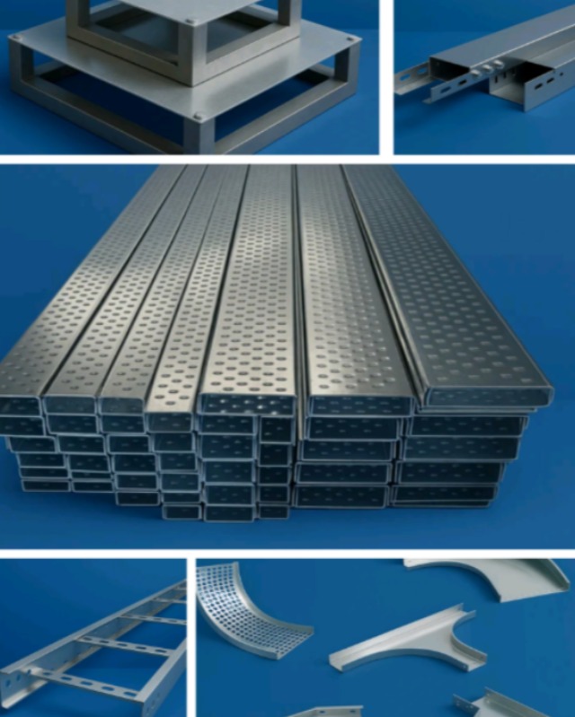
Straight cable tray sections form only part of a cable-management route. Most installations also require bends, tees, reducers, couplers, covers, supports, and fastening components. If these accessories do not match the main tray, site teams may face alignment problems, weak joints, and unplanned fabrication work.
Devansh Enterprises manufactures cable tray accessories for perforated, ladder, and other cable-support systems. Selecting accessories alongside the main trays helps create a coordinated installation rather than a collection of incompatible components.
Essential Accessories for Cable Tray Routes
The exact accessory list depends on the approved route drawing. Common components include:
- Horizontal bends
- Internal vertical bends
- External vertical bends
- Tee sections
- Cross sections
- Left-hand and right-hand reducers
- Centre reducers
- Coupler plates
- Covers
- Dividers
- Cantilever brackets
- Ceiling supports
- Hold-down clamps
- Fasteners and earthing jumpers
Each item performs a specific role in changing direction, joining sections, supporting the route, or protecting the installed cables.
Accessory Planning for Pune Industrial Projects
Factories and commercial developments in Pune often include congested service areas containing pipes, ducts, structural members, and electrical systems. Correctly designed accessories allow cable trays to navigate these obstacles without creating sharp cable turns.
Projects in Chakan, Ranjangaon, Bhosari, and Talegaon may also require heavy-duty supports for machinery-related power routes. Commercial facilities in Hinjawadi and Kharadi may need compact bends and dividers for data, communication, and building-service cabling.
A route survey and coordinated drawing can identify accessory requirements before material reaches the site.
Check Dimensional Compatibility
A bend described as 300 mm wide will not necessarily fit every 300 mm tray. Side-rail profile, flange dimensions, sheet thickness, hole spacing, and joining method must also match.
Before placing an order, verify:
- Tray width and depth
- Side-wall profile
- Material thickness
- Coupler-hole pattern
- Bend radius
- Surface finish
- Cover type
- Fastener specifications
Using accessories from the same manufacturing system usually reduces compatibility problems.
Review Bend Radius and Cable Protection
Power, control, data, and fibre cables have different bending limitations. A sharply fabricated bend may place excessive stress on the cable or make pulling difficult.
The selected cable tray accessories manufacturer should produce transitions that support the project’s minimum cable bending radius. Edges must be smooth, and joints should not leave projections that can cut or abrade cable insulation.
Reducers also need careful selection. Sudden width changes can compress cables or create uneven loading if the transition is not planned properly.
Match the Surface Protection
Accessories and supports should have a finish compatible with the main cable trays. Installing hot-dip galvanised trays with untreated brackets can create weak points where corrosion begins earlier.
The same principle applies to covers, couplers, fasteners, and suspended support systems. Project specifications should state whether the route requires pre-galvanised, hot-dip galvanised, powder-coated, stainless-steel, or another approved finish.
Prepare an Accurate Material Schedule
An accessory schedule should be prepared from the final tray layout rather than estimated from the total route length. It should include component type, size, quantity, material, coating, and associated hardware.
A small allowance may be useful for couplers and fasteners, but complex bends and junctions should be ordered according to actual drawings.
Pune contractors and project teams can submit their route layout and tray specifications to Devansh Enterprises for coordinated accessory planning. Confirming every transition and support component before dispatch can reduce installation delays and minimise last-minute site fabrication.