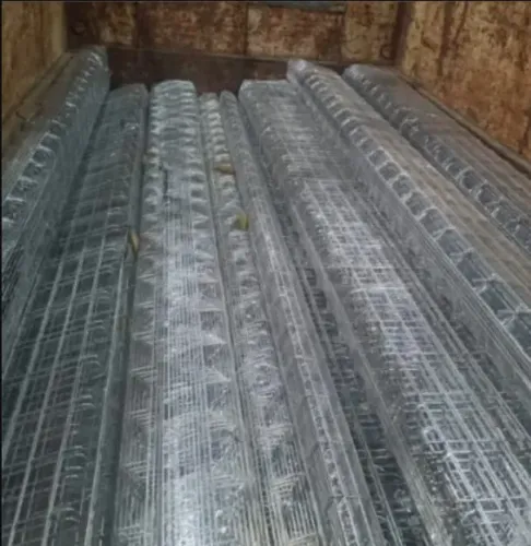

A perforated tray that looks rusty is not automatically a replacement case, but a buckled rail, weakened support point or failed joint can put cables and workers at risk. By checking the structure, measuring the installed system and planning isolation correctly, you can decide whether to repair one section or replace it with a compatible tray system.
Key takeaways
- Inspect tray surfaces, supports, cut edges, splice plates, and clamps after monsoon exposure.
- Replace sections with perforation, distorted steel, failed joints, or unsafe load-bearing supports.
- Measure tray width, side height, length, bends, levels, covers, and support spacing before ordering.
- Request material, finish, thickness, load data, accessories, and delivery details in the quotation.
Inspect the tray after Pune’s monsoon before deciding
During perforated cable tray maintenance in Pune, inspect the top, underside and support steel after the monsoon, flooding, process leaks or chemical wash-down. Record standing water, mud deposits, chemical residue, white rust, red rust, and corrosion concentrated at cut edges, drilled holes, splice plates or support clamps.
- Check side rails, rungs, bends and vertical transitions for deformation, cracks, detached sections and failed welds.
- Check cut edges, perforations and bolt holes for sharp metal, blockage or elongation.
- Check splice plates, fasteners and supports for missing hardware, looseness or movement.
- Check cables for sag and contact with sharp metal; photograph every defect, mark its route location and record the span between supports.
| Finding | What to record | Why it matters |
|---|---|---|
| Broad white or red discolouration | Area, depth and coating condition | Surface colour alone does not prove structural loss |
| Corrosion beneath a splice or on the underside | Section loss, affected length and fastener condition | Hidden local damage can weaken the load path more than widespread staining |
| Loose support or cable sag | Support type, spacing and cable contact | Movement can overload joints and damage insulation |
Treat the tray, joints, supports and accessories as one tested mechanical system under IEC 61537. Do not approve repair from appearance alone: a clean-looking underside can hide serious section loss, while broad surface discolouration may leave strength intact. A qualified assessment must decide whether the recorded damage permits repair or requires replacement.
Use structural condition to choose repair or replacement
A repair is technically sufficient only when the damage is confined and the tray still has its original load path, cable clearance, bonding continuity and corrosion protection. Cleaning mud or deposits, tightening sound fasteners, replacing a failed splice plate, adding a properly designed support or restoring a small coating defect can solve that problem.
| Repair | Accept when | Reject when |
|---|---|---|
| Cleaning or hardware work | The rails, rungs, holes and supports remain sound | Corrosion has materially reduced the section or cables still touch sharp metal |
| Splice or support repair | Approved hardware restores the tested arrangement | A side rail is buckled or cracked, a rung or weld has detached, or bolt holes are elongated |
| Section replacement | The damaged length is short and the original profile and hardware remain available | Damage is widespread or existing supports cannot be verified against the new load table |
An improvised plate or extra bolt is not automatically equivalent to the original IEC 61537 configuration. Obtain a specifically designed repair and qualified engineering approval before altering a load-bearing member.
Keep splice joints away from supports, following the manufacturer’s installation instructions and NEMA VE 2 guidance. A joint directly over a support changes bending behaviour and can overload splice hardware. On long outdoor runs, use the manufacturer’s sliding-joint gap setting at the installation temperature and provide separate bonding across the movement joint.
Replacement is more defensible when the profile, coating or hardware is unavailable. That is the safer decision for perforated tray repair or replacement in Pune and for perforated tray replacement in Pune when support capacity or load data cannot be verified.
Measure the installed system before ordering a replacement
A replacement that fits the width can still fail its load, clearance or corrosion requirements. For perforated tray replacement in Pune, measure the installed system before requesting a quotation.
1. Record tray width, side-rail height and profile, straight-section length, standard tray length, perforation pattern, material, coating, fastener size and cover requirement. Measure each bend, tee, reducer and vertical fitting rather than assuming matching catalogue geometry.
2. Map support spacing, span direction, support type and the location of every splice. Match allowable load at the actual span; IEC 61537 performance for load and deflection depends on material, perforation, rail depth, span, support arrangement, splice type and installation orientation, not width alone.
3. Check cable fill, separation, bending radius and future capacity before accepting a narrower tray. Record covers, bonding accessories and every thermal expansion joint, including the manufacturer’s required gap.
4. For field-cut galvanized sections, specify deburring and coating restoration under ASTM A780/A780M. Zinc-rich paint, zinc-based solder and sprayed zinc are recognised repair methods; ordinary enamel is not an equivalent zinc repair.
Photographs alone cannot show every dimension. Submit photographs, a marked-up route drawing and a dimension sheet showing fittings, supports and splices; together they prevent a technically wrong substitution ordered as “300 mm tray” alone. Include the existing tray’s load-table reference and any unusual orientation or support condition.
Plan isolation and carry out the repair without damaging cables
Do not remove a damaged tray until the circuit status and cable support plan are confirmed. For perforated cable tray maintenance in pune, obtain the project electrical permit, identify every circuit and cable, confirm the shutdown, lockout or isolation method, and verify that connected equipment is safe under the site electrical procedure.
1. Photograph each cable, label both ends and record its route before moving anything. Install temporary supports rated for the cable weight, spacing and minimum bending radius. Never leave cables hanging from terminations while removing the tray or a support.
2. Set a lifting limit for the tray section and use controlled handling. Protect insulation from scraped edges, uncontrolled swinging and contact with removed hardware.
3. Remove mud, standing contamination and corrosion products. Tighten sound fasteners, replace damaged hardware, and install the approved splice at the specified location. Deburr field cuts and restore damaged galvanizing with a compatible zinc-rich coating where appropriate; ordinary enamel is not an equivalent zinc repair.
4. Align every support and inspect the repaired section for sharp contact points. Re-establish mechanical continuity and electrical bonding with approved jumpers or other specified provisions. A metallic tray is not automatically the protective conductor.
5. Before removing temporary supports, recheck tray level, support spacing, splice position, cable separation, sag, covers and expansion gaps. Close the permit only after recording photographs, measurements, hardware details and the completed inspection.
Compare tray options and request a technically complete Pune quotation
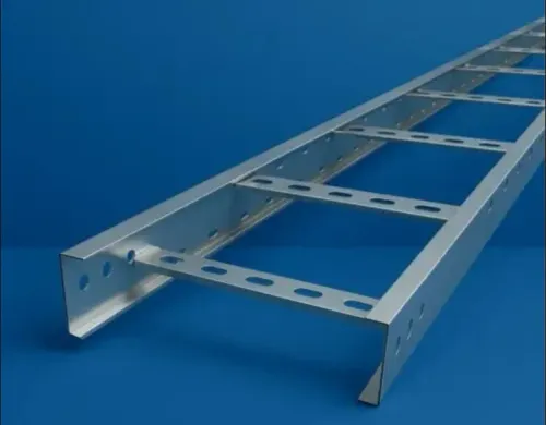
Compare the replacement by environment and system performance, not by width alone. A new GI perforated tray suits routine indoor or sheltered routes where ventilation and drainage matter. Hot-dip galvanised tray gives stronger coating protection for exposed routes, including Pune’s wet season, but cut edges and damaged areas still need compatible treatment.
| Option | Strength | Limitation |
|---|---|---|
| GI perforated steel | Ventilation and drainage for sheltered routes | Exposed cut edges need coating repair |
| Hot-dip galvanised steel | Better protection for outdoor exposure | Damaged zinc still needs treatment |
| Powder-coated steel | Finished surface and colour coding | Painted joints do not guarantee metal-to-metal bonding |
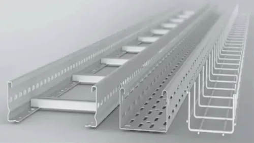
| Solid-bottom tray | Better debris control and cable separation | Drains poorly and can retain water |
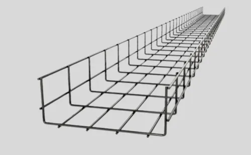
| Wire-mesh tray | Fast modification, access, ventilation and drainage | Changes segregation, support and cable-restraint details |
| Aluminium or stainless steel | Consider for confirmed corrosive exposure | Check dissimilar-metal contact at joints and supports |
For a perforated tray replacement in Pune, ask a perforated cable tray supplier in Pune to state:
- Tray designation, material, coating, side-rail depth, standard length and perforation pattern
- Allowable load at the actual project span, with support spacing and installation orientation
- Splice hardware, covers, bends, reducers, vertical fittings and fastener sizes
- Earthing or bonding accessories, since painted or coated joints cannot be assumed electrically continuous
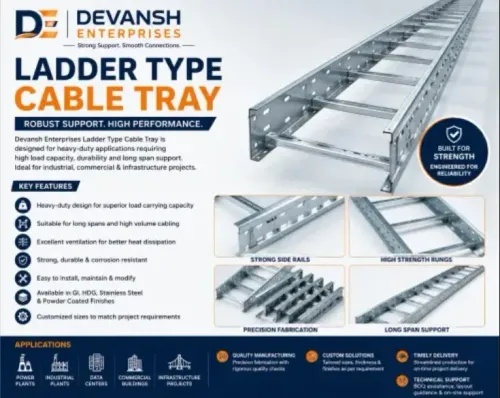
Devansh Enterprises can be included in the comparison, but check its quotation against these details rather than width, length and gauge alone.
Related products
 | GI Perforated Cable Trays Manufacturers in Pune,PCMC, Maharashtra Welcome to Devansh Enterprises - one of the leading Cable Tray Manufacturer in Pune, PCMC and Maharashtra, we are leading GI Perforated cable trays... View product → |
 | Cable Tray Manufacturer Devansh Enterprises manufactures high-quality Perforated Cable Trays designed to provide efficient, safe, and organized cable management solutions... View product → |
Frequently asked questions
When should you inspect a perforated cable tray in Pune?
Inspect it after the monsoon, flooding, process leaks, chemical wash-down, or any event that leaves standing water, mud, residue, white rust, or red rust. Check the top, underside, cut edges, drilled holes, splice plates, clamps, and support steel.
Should you repair or replace a perforated cable tray?
Repair when corrosion is superficial and the tray, joints, and supports remain straight and load-bearing. Replace sections with perforation, severe section loss, distortion, failed splice connections, loose supports, or damage that reduces cable protection.
What measurements are needed for perforated tray replacement in Pune?
Record tray width, side height, length, straight runs, bends, tees, reducers, elevation changes, cover requirements, support spacing, cable fill, and existing connection details. Photograph labels and measure the installed system before ordering.
How can you repair a cable tray without damaging installed cables?
Plan isolation with the electrical team, identify and protect circuits, provide temporary cable support, remove damaged sections in controlled stages, and keep cut edges away from cables. Restore bonding, joint hardware, supports, and covers before re-energisation.
Related product
 | Cable Tray Hot Dip Perforated Type Cable Tray Manufacture Pune In PCMC And All Maharashtra Hot Dip View product → |
Keywords